

This is a little project of mine, creating a custom computer peripheral for one of my
Motivation
I have been playing ARMA 3 for years now, not in small parts thanks to those guys. One evening playing with them I find myself, as so often, in need of passing on a compass direction to my teammates.
It just so happened that that evening I had my hiking compass lying on my desk in front of me. Almost out of reflex I looked down on that compass instead of opening the one ingame.
My immediate thought on noticing my mistake was somewhere along the line of “oh man, would be cool if it would display my ingame orientation”. The idea stuck and the result can be seen in the video linked above.
Project Overview
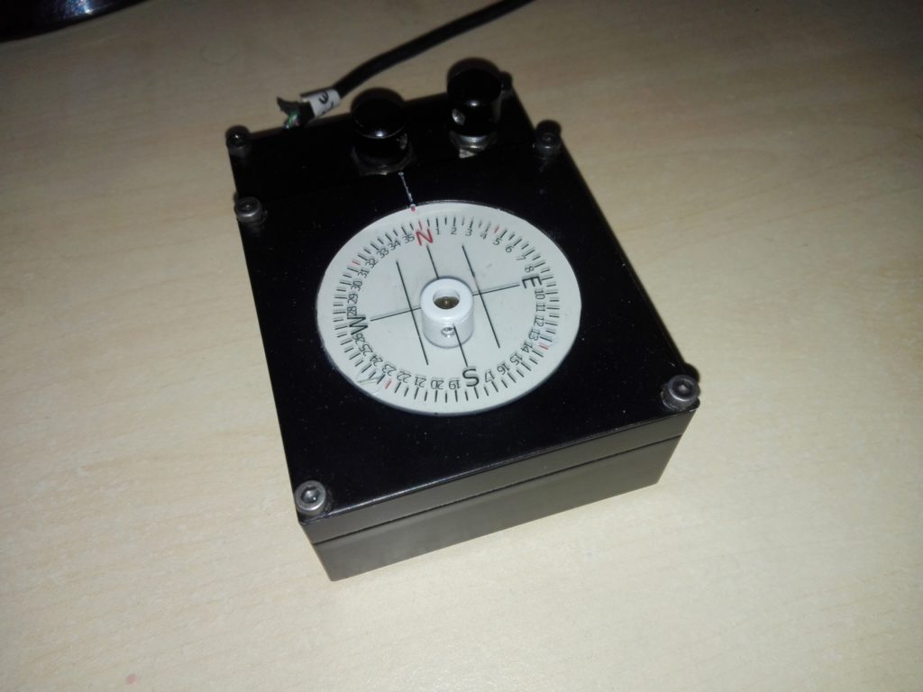
The project is built upon an Arduino Metro Mini. The compass scale is printed onto an overhead projector sheet and sits on a stepper motor. A rotary encoder turns the scale to manually adjust it to the initial
On the software side, the project is split into three parts. There is the code running on the Arduino. A separate application receives new directions via
Wiring
I will not go into great detail about the hardware used. I am not very qualified to write about those things and other people have written great tutorials for all parts used here. I will link everything you need to build this on your own.
The parts used are:
- Adafruit Metro Mini
- 28BYJ-48
- KY-040
- PC16SH
- LED (+ resistor)
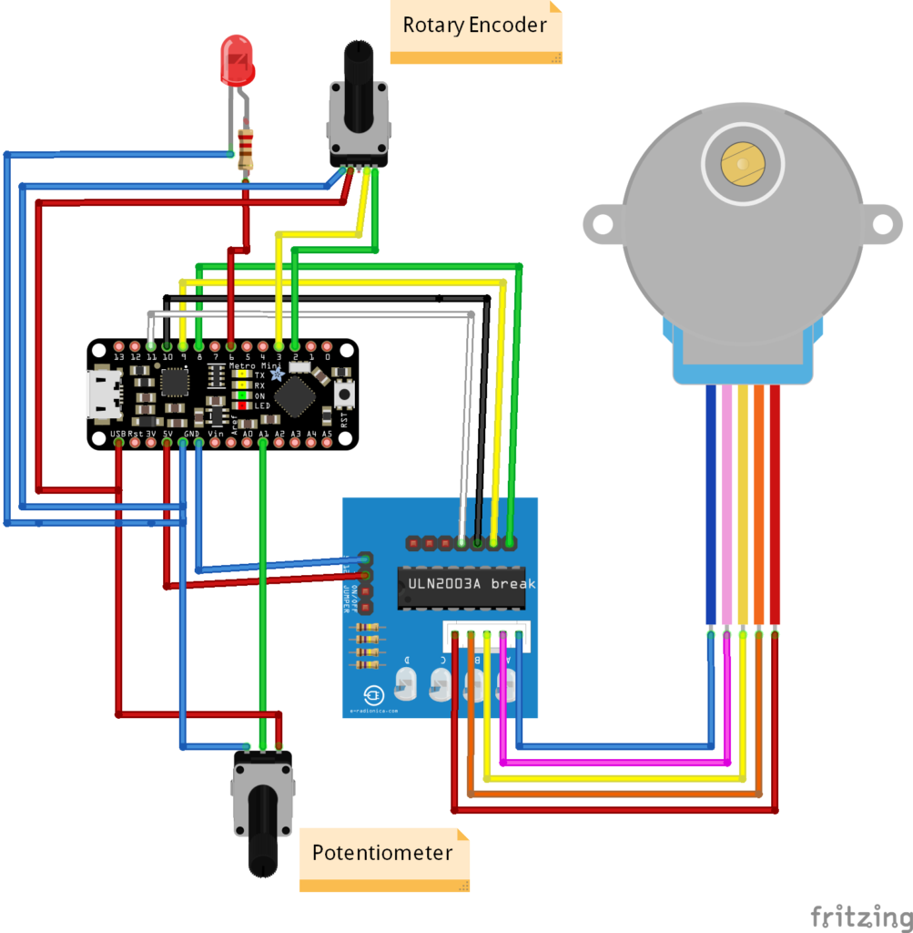
The stepper motor used is a 28BYJ-48. The motor itself is connected to the driver board (a ULN2003 in this case). The driver board connects to the Arduino itself. The + pin on the board is connected to the 5V pin on the Arduino, while ground connects to ground of course.
The pins IN1 through IN4 on the driver board are connected to digital pins 8 through 11 on the Arduino respectively.
Michael Schoeffler has a great article on using this stepper motor with Arduinos if you want a more in-depth explanation. As he points out there is also a caveat when connecting the motor directly to the Arduino for power supply.
Ideally, the motor would be connected to an external source. However, in this
The rotary encoder is a KY-040. It connects to the USB pin on the Arduino for power, and to ground of course. The DT and CLK pins on the encoder connect to digital pins 2 and 3.
Note that the DT and CLK pins ideally connect to interrupt pins on the Arduino. See the documentation of the Encoder library for details.
Connecting the LED is pretty straight forward. The ground pin connects to ground, while the + pin connects to one of the digital pins, pin 6 in this case. This way the LED can be dimmed. Make sure that you put the correct resistor between the digital pin and the + pin for the LED you use.
The potentiometer connects to the analog pin A1, and ground and USB (power) of course.
The video below shows the components (minus the LED and potentiometer) at an early stage of development. So you see all the innards exposed.
Code
The coding part of this project is split into three modules: the Arduino code, the game plugin, and a compass server to communicate between the former two.
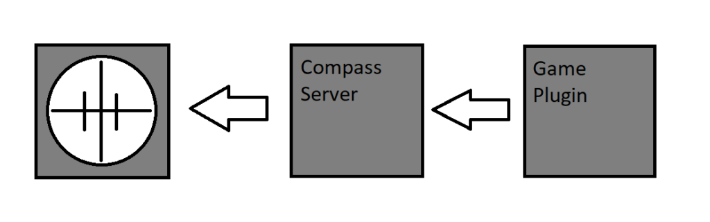
Adding the server application in between removes a lot of responsibility from the game plugin. This is good since the server as such is much easier to debug and maintain than the plugin.
I’m providing all the code in git repos. I will try to concisely describe all the essential parts below.
Arduino Code
You can find the complete source code On Github. I will only discuss the key elements here. I will not discuss how to control the hardware parts here. Check out the stepper motor and rotary encoder libraries if you want more details on that.
The main loop of the code performs a few steps to update the compass scale and the backlight. In abridged code it reads something like this.
void loop()
{
  // update backlight
  _brightness = readPotentiometer();
  setLEDBrightness (_brightness);

  // get encoder position
  _encoderPos = readEncoderPos();
  _encoderDiff = _encoderPos - _lastEncoderPos;
  _lastEncoderPos = _encoderPos;

  // get target direction to be displayed by the compass
  _targetDir = readSerialInput();
  _rotationSteps = calculateSteps(_targetDir);

  // rotate the compass scale
  _stepper.step(_rotationSteps + (_encoderDiff * _calibrationSpeed));
}
Noteworthy are the
This however means that I might end up cutting of the end of messages and therefore ending up with an incorrect direction. I mitigate this by the use of tokens to mark the end of a message.
Messages are aggregated in a string buffer. The buffer may contain multiple messages and end with an incomplete message. To deal with this, only the last complete message is used and taken to be the new target direction for the compass.
"113;121;127;12"
Take this string as an example. ‘;’ is the token to separate messages. The last complete message is “127”. Everything before that will be discarded as it is already in the past. “127” is set as the new target direction. Everything after that will be kept in the buffer because the rest of the message is expected to come in later.
In abridged code it looks something like this:
void readSerialInput()
{
  _input += Serial.readString();

  if((idx = _input.indexOf(';')) > -1)
  {
    if(idx == _input.length() -1)
    {
      // token is at the very end
      _targetDir = _input;
    }
    else
    {
      // cut away incomplete message
      _tmpStr = _input.substring(0, _input.lastIndexOf(';'));

      // cut away old messages
      while((tmpIdx = _tmpStr.indexOf(';')) > -1)
      {
        _tmpStr = _input.substring(tmpIdx+1, _tmpStr.length());
      }

      _targetDir = _tmpString;

      // keep incomplete message for later
      _input = _input.substring(idx+1, _input.length());
    }
  }
}
Firstly the target direction is converted to steps from
Next, simply subtract the current direction in steps from the target direction in steps. If the resulting step count is more than half a revolution, the direction is reversed.
In abridged code it looks something like this:
int calculateSteps(int targetDir)
{
  stepsToTurn = targetDir - _currentDir;

  if(stepsToTurn > _stepsPerRotation / 2)
  {
    stepsToTurn = targetDir - (_currentDir + _stepsPerRotation);
  }
  else if(stepsToTurn < -(_stepsPerRotation / 2))
  {
    stepsToTurn = (targetDir + _stepsPerRotation) - _currentDir;
  }

  return stepsToTurn;
}
One last thing to handle is that the player may turn around quickly, while the motor speed is pretty limited. In the worst
To mitigate this the amount of steps the motor is allowed to turn during each update cycle is limited. This allows the target direction to change before the compass scale has reached the old one, therefore the compass can react much quicker to fast player movement.
Compass Server
You can find the complete source code On Github. I will only discuss the key elements here.
The compass server exists to receive messages via socket from the game plugin, described below, to the compass itself, described above.
To achieve this it has three distinct modules. Firstly it creates a server listening to a predefined port. Secondly, it sends and receives messages via
The server code is directly taken from this example on the Microsoft website. The only noteworthy addition is a slot for a callback function to pass on incoming messages to the applications message buffer.
Similarly the serial port code is simple and mostly taken from an available example.
The message buffer connects the server and the serial port. It maintains two message queues, a read- and a write-queue. Incoming messages from the server are put into the
Periodically, a message is taken from the read-queue to be sent to the compass via
void MessageBufferLoop()
{
  while(true)
  {
    if(_readBuffer.empty() == false)
    {
      writeToSerialPort(_readBuffer.Dequeue());
    }
    else
    {
      _readBuffer = _writeBuffer();
      _writeBuffer = new Queue<string>();
    }
  }
}
At the same time, the serial port is checked for incoming messages.
The server application also has a rudimentary GUI to display incoming and outgoing messages. It also allows to manually send messages to the compass for testing and debugging.
Arma Plugin
You can find the complete source code On Github. I will only discuss the key elements here.
This project consists of two parts. Firstly the ARMA 3 mod, and secondly a .dll file.
The mod is nothing more than a script that periodically calls the .dll with the current compass direction of the player.
while{true}
do
{
  _d = direction player;

  _result = "CompassClient" callExtension ["updateCompass", [_d]];

  sleep 0.1;
};
The important part here is callExtension. This is how the .dll is called. Check out the documentation for details.
The dll passes on the compass direction via socket to the Compass Server.
void updateCompass(float direction)
{
  // open socket on local host with port 56172

  // send direction

  // close socket (no answer expected)
}
This function uses
To be usable as an ARMA 3 extension the dll needs to implement the API described in the documentation.
extern "C"
{
    __declspec (dllexport) void __stdcall RVExtensionVersion(char* output, int outputSize);
    __declspec (dllexport) void __stdcall RVExtension(char* output, int outputSize, const char* function);
    __declspec (dllexport) int __stdcall RVExtensionArgs(char* output, int outputSize, const char* function, const char** args, int argsCnt);
}
RVExtensionArgs parses the argument given by the calling script above and passes it on to updateCompass.
int __stdcall RVExtensionArgs(char* output, int outputSize, const char* function, const char** args, int argsCnt)
{
  if (strcmp(function, "updateCompass") == 0)
  {
    if (argsCnt >= 1)
    {
      updateCompass(atof(args[0]));
      strncpy_s(output, outputSize, "updating compass", _TRUNCATE);
    }

    return 100;
  }

  strncpy_s(output, outputSize, "void", _TRUNCATE);

  return 0;
}
Known Issues and further Development
The stepper motor used in the project, the 28BYJ-48, is not the most precise piece of hardware you will ever find (it is however possibly the cheapest stepper motor you will find). As a result the compass does not always perfectly display an exact direction. In
To learn more about the issues involved when using this specific motor check out this great article by
Precision-issues aside, there are some features I didn’t end up implementing. The possibly most interesting one would have been automatic calibration.
Since stepper motors do not have knowledge of their current orientation some other way to determine this information would be necessary. I only have vague ideas for that. I could imagine using a simple mechanical switch or maybe a hall-sensor.
I intend to look into bringing this project to different games in the future. Basically, any game that offers sufficient modding-support is fair game.
Acknowledgement
Thanks to the guys of FHQ for helping out with the ARMA plugin.
Thanks to my father, basically all the credit for the awesome aluminium case goes to him.
Also thanks to all the guys in CiA for keeping the game fun to play after all those years.
And of course thanks to Bohemia Interactive and Arduino for making this project possible.
Resources
- https://www.mschoeffler.de/2017/09/23/tutorial-how-to-drive-the-28byj-48-stepper-motor-with-a-uln2003a-driver-board-and-an-arduino-uno/
- https://www.arduino.cc/en/Reference/Stepper
- http://henrysbench.capnfatz.com/henrys-bench/arduino-sensors-and-input/keyes-ky-040-arduino-rotary-encoder-user-manual/
- https://www.pjrc.com/teensy/td_libs_Encoder.html
- https://www.arduino.cc/en/tutorial/fade
- https://www.instructables.com/id/How-to-use-Potentiometer-Arduino-Tutorial/
- https://docs.microsoft.com/en-us/dotnet/framework/network-programming/asynchronous-server-socket-example
- https://www.instructables.com/id/Serial-Port-Programming-With-NET/
- https://docs.microsoft.com/en-us/windows/desktop/winsock/winsock-client-application
- https://community.bistudio.com/wiki/callExtension