As a live-long aviation enthusiast I’ve been playing flight simulators since childhood. For about as long as that I had a fascination for associated computer peripheries, joysticks, pedals and such. Anything to improve the illusion of sitting in an actual cockpit.
So anyways, here is my attempt at inflating my pants.
Table of Contents
Motivation
If you are in the know about military aviation you will already have guessed that my pants-inflation endavours have very little no sexual motivation. Instead this is an attempt at creating haptic feedback for G-Forces experienced in flight (-simulation).
Actual G-Forces have a number of effects on the human body. For starters, there is that stomach-drop sensation that most people will know from either flying commercially or maybe from riding a roller coaster. With increasing severity, there is the onset of tunnel-vision, culminating in loss of consciousness.
I am over-simplyfing for brevity, but in any case I don’t know enough about the human body to (safely) simulate any of those effects (within budget…). So instead I decided to create a little desktop version of a pilot’s g suit.
Simplyfied, to combat the effects of G-Forces fighter pilots wear inflatable pants to help pushing blood up from the legs. The approach of recreating this equipment provides both usefull haptic feedback and is at least related to what a real fighter pilot would feel during flight.
Project Overview
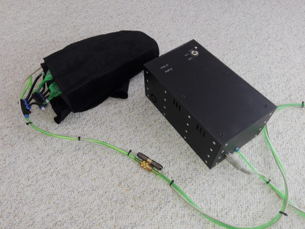
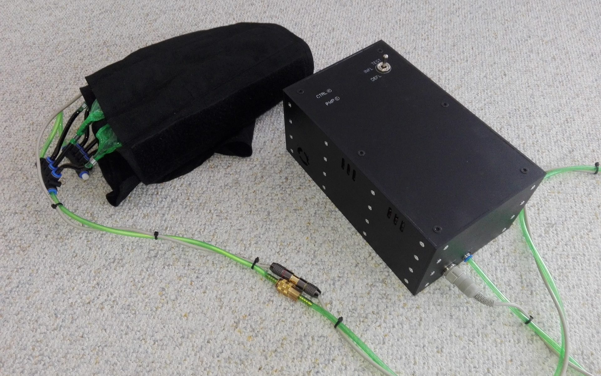
This project is an attempt at creating a g suit like computer periphery for use with flight simulators. Leg-wraps with internal air chambers inflate proportionally to increased g loads experienced by the player to create pressure on the legs. This pressure sensation provides feedback to the player about ingame forces without having to read on-screen dials.
Other than real g suits it covers only the upper thighs. This reduces the internal volume and makes it easier and quicker to in- and deflate them. It also makes it easier and quicker to set the whole thing up and put it on.
The hardware for this project consists of two components
- A box providing air supply
- Leg-wraps with inflatable air-chambers
The box houses six small air pumps and an Arduino Leonardo. I just happen to have a few Leonardos lying around, most other models will do just as fine. The pump motors are controlled with Serial Controlled Motor Drivers from SparkFun. At time of writing those are unfortunately discontinued.
The box also has two little fans to keep the motor drivers and the motors cool, two LEDs to indicated power supply to the Arduino and the motor drivers and an (on)-off-(on) switch for testing.
The leg-wraps are simple fabric strips that close with velcro and have pockets to hold inflatable plastic tubes. The plastic tubes are connected with silicon and plastic tubing, and standard pneumatic connectors with 6mm outer diameter.
One of the plastic tubes contains a pressure sensor. This enables mapping of G-Forces to air-pressure.
The software for this project has three components. The code running on the Arduino controls the pumps and provides serial communication via a simple protocol. A standalone desktop application communicates with the Arduino and receives G-Forces as floats via TCP socket. Lastly there is the DCS plugin which simply passes on the player’s current G-Force.
The source code is available on github (Server, Arduino, Plugin).
Hardware
As stated in Project Overview most of the electronic components are housed in a box with air pumps.
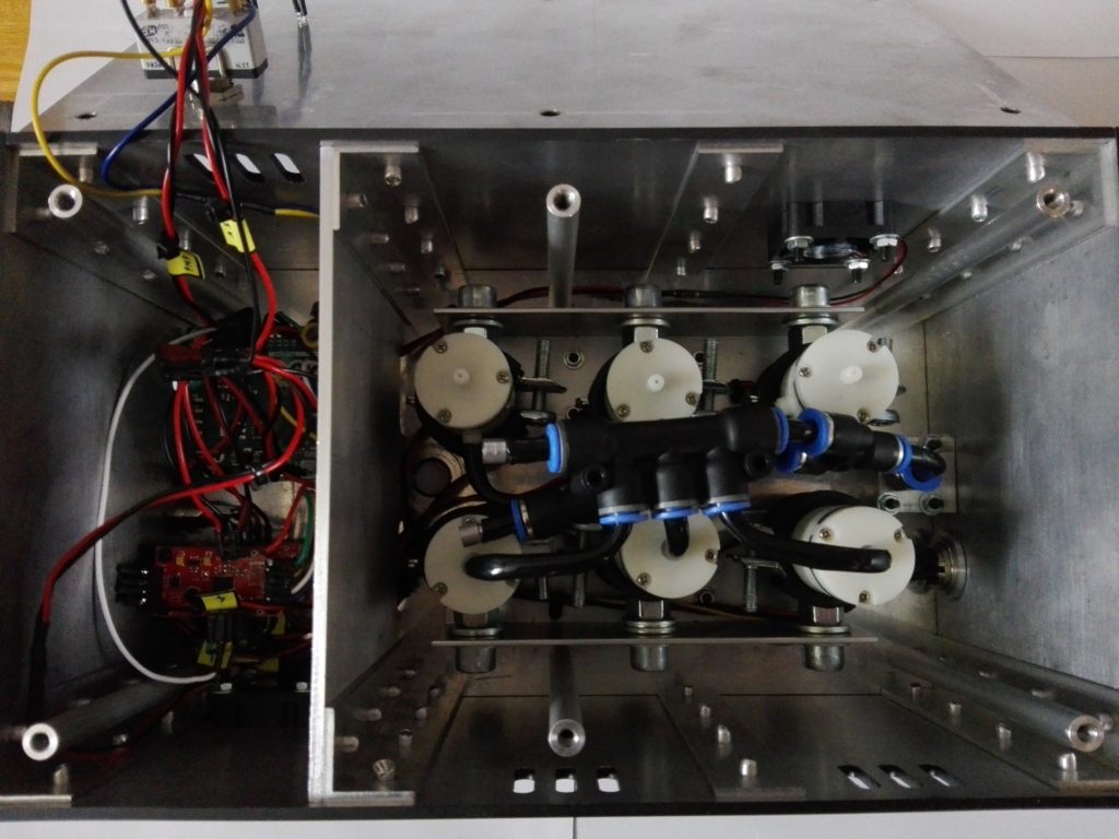
The electronics compartement is somewhat compact and difficult to photograph. The wiring will be explained in detail below.
The six air pumps are arranged in two groups, one for inflation and one for deflation. This type of pump does blow the same way regardless of engine direction, therefore the two groups are needed.
The tubes coming from the pumps all combine into one single outlet. The software only ever runs one of the two pump groups, therefore only one outlet is needed.
The outlet connects to a silicon tube ending in a pneumatic coupling. A cable with 4 wires to connect a pressure sensor runs along the tube and ends in a 4-pin plug.
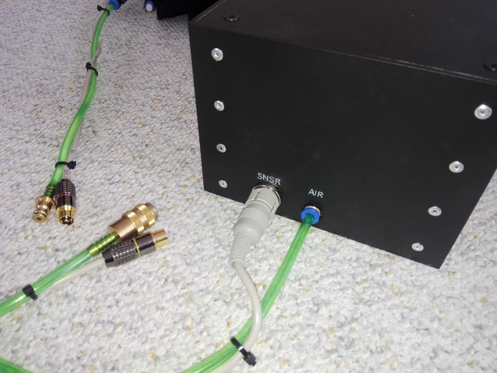
The second and final part of the hardware setup is a pair of leg-wraps covering the user’s upper thighs. The wraps are constructed from cotton fabric and close with 5 cm velcro strips. Each wrap has 3 pockets for air chambers.
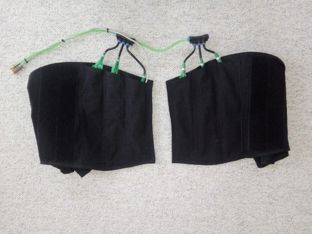
The air chambers are made from PE foil because this material is well suited to be welded with a heat gun. Each chamber connects to a pneumatic splitter via a tube. One of the chambers contains a GY-BMP280 pressure sensor. This sensor is used to control inflation of the air chambers. The idea is to map a range of G-Forces to a pressure range.
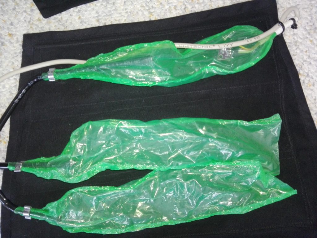
A given force fn translates to a pressure pn. The pumps are used to reach and maintain pn within a given tolerance until the given force changes.
The air tube running from the air chambers and the cable running from the pressure sensor end in the counter parts to the coupling and plug coming from the pump box.
Wiring
The electronic components for this project consist of
- Arduino Leonardo (without headers)
- 3 x SparkFun Serial Controlled Motor Driver
- SparkFun Logic Level Converter
- 6 x DC Air Pump
- GY-BMP280 Pressure Sensor
- 2 x 30mm DC Fan
- (on)/off/(on) Toggle Switch
- 2 x LED (+ resistor)
This list excludes some simple parts like power plugs and cable connectors.
There is no specific reason to use the Leonardo board, other than that’s what I had lying around. If you opt for a different board note that the pinout on the Leonardo is somewhat different from most other similar ones like the Uno. The descriptions below are based on the Leonardo but I will try to point out relevant differences.
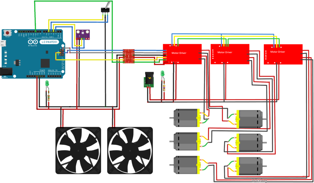
I was not able to find Fritzing files for all the components, most notably the motor driver. Therefore parts of the diagram look a bit artisanal. The 6 pumps are represented as motors in the diagram, but that’s basically what they are anyways.
The specific motor drivers used in this project were chosen because they are chainable to control more than 2 motors without running out of pins on the Arduino. Up to 16 drivers can be chained with two motors each, for a total of up to 32 motors.
The hookup guide shows how to connect to an Arduino (or SparkFun board). Especially example 3 in the guide is relevant to this project.
NOTE that the Arduino Leonardo’s pinout differs from the RedBoard in the guide as well as Arduino Uno. Importantly the SCL, COPI, and CIPO pins are in a different position. They are found among the 6 ICSP pins oposite from the USB connection. Refer to the page 3 of the official pinout diagram. Pin 10 as chip select is the same as in the hookup guide though.
To limit the load on the drivers at any given time I did connect one inflation and one deflation motor each. Therefore only ever one engine per driver will be running.
The motor drivers have pins for an external power supply for the motors. I use a 9V power supply with 3000 mA, indicated by the standalone socket in the diagram. Each pump motor draws up to 500 mA according to the documentation. However, using an adjustable lab power supply I measured more than that, so I recommend some headroom.
One LED (with resistor fitting for 9V supply) connects directly to the socket.
The pressure sensor uses i2c communication and therefore connects to the SDA and SCL pins (as well as ground and 5V).
NOTE that the SDA and SCL pins on the Leonardo are again placed differently than on similar boards. Refer to page 2 of the pinout diagram.
The outer pins of the toggle switch connect to digital pins 4 and 5, the center pin on the switch connects to ground. Since the switch I use does not lock on either of the outer positions it basically behaves like two buttons.
One LED (with a resistor fitting for 5V supply) and the two cooling fans connect directly to the Arduino’s 5V and ground pins.
Code
The code for this project consists of three components

The following discussion only covers some of the more noteworthy elements. The full code is available in the linked repositories.
The code running on the Arduino in the pump box controlls the pumps (suprise…) to reach and maintain a given pressure value within the leg-wraps’ air chambers.
The G Suit Server is a standalone desktop application that implements the serial communication with the Arduino and provides a simple GUI for testing and debugging. The server listens to a TCP port to receive G-Force magnitudes from external sources (typically a flight simulator…DCS perhaps…).
The DCS plugin simply sends current G-Forces to the G-Suit Server.
Arduino Code
The Arduino code is mainly responsible for controlling an array of six air pumps. As mentioned in the Wiring section, the pump motors are controlled by three SparkFun Serial Controlled Motor Drivers using the corresponding library. A GY-BMP 280 sensor is used to messure pressure inside air chambers, using the BMP280 library.
The setup function will block until both the motor drivers and the pressure sensor are initialized to make sure everything works as intended, or better not at all. The setup code for the motor drivers is based on the hookup guide (example 3), omitting the bridging part.
The pump control is programmed to inflate the connected air chambers (mentioned in the Hardware section) to a given pressure. To do so the environment pressure is taken and stored immediatly after initialization. During runtime the reference pressure is continuously updated when the pumps were inactive for 60 seconds.
The idea is that, since the air system is not completely airtight the pressure inside will have normalized to environment levels after 60 seconds. This continuous updating prevents weird behaviour if the environment pressure changes significantly (e.g. significant weather changes).
void calibrate()
{
  /*
  setDeflationSpeed(PUMP_SPEED);

  delay(1000);

  setDeflationSpeed(0);

  delay(10000);
  /**/

  if(_sensorIsAvailable == true)
  {
    _referencePressure = _bmp.readPressure();

    PrintLine("Calibrated Reference Pressure = " + String(_referencePressure));
  }
  else
  {
    PrintLine("Pressure Sensor is not available");
  }

  _sensorIsCalibrated = true;
}
Note that deflation before taking the reference value is disabled because it actually creates a slight vacuum if the chambers were empty to begin with.
The main pump control logic is implemented in the handleTargetPressure function. If a target pressure is set the code will attempt to inflate or deflate the air chambers until the target is met within a slight tolerance. Note that target pressures are given as offset to the environment pressure.
void handleTargetPressure()
{
  float pressure = _bmp.readPressure() - _referencePressure;

  if(_targetSet)
  {
    float diff = _targetPressure - pressure;
    float absDiff = abs(diff);

    // PrintLine(String(_targetPressure) + " - " + String(pressure) + " = " + String(diff));

    if(absDiff > 20.0f) // get positive, diff > 50
    {
      float pf = 1.0f;

      if(absDiff < PUMP_REG_LIMIT)
      {
        pf = constrain(absDiff / PUMP_REG_LIMIT, 0.2f, 1.0f);
      }

      if(diff > 0.0f)
      {
        setDeflationSpeed(0.0f);
        setInflationSpeed(PUMP_SPEED * pf);
      }
      else
      {
        setInflationSpeed(0.0f);
        setDeflationSpeed(PUMP_SPEED * pf);
      }
    }
    else
    {
      setInflationSpeed(0.0f);
      setDeflationSpeed(0.0f);
      if(_targetPressure <= 0.0f)
      {
        _targetSet = false;
      }
    }
  }
}
If the pressure difference to the target is lower than PUMP_REG_LIMIT, but higher than the tolerance value the pump speed is progressively limited to compensate for measurement latency. Otherwise the pumps are run at a given maximum speed.
If a target pressure of 0 was given (remember, targets are offsets from environment pressure) the target pressure will be discarded once it has been reached. This means active pressure regulation ceases until a new non-zero target is given.
The readSerialInput function implements a simple serial communication protocol. The implementation is straight forward and will not be discussed in detail. The messages are
- PUMPITUP (challenge to be sent by the Server application)
- HITTHEJAM (response to be sent by the Arduino after the challenge message was received)
- INFL (run inflation pumps, to be sent by server)
- DEFL (run the deflation pumps, to be sent by server)
- STOP (stop all pumps, to be sent by server)
- REBOOT (experimental, send a reboot impulse to motor drivers, to be sent by server)
- SET_PRESSURE<float> (set the target pressure, to be sent by server)
All messages end with a delimiter character, ‘;’.
The main loop make sure that the reference pressure is set, handle serial and test switch input, verify the motor drivers and pressure sensor are connected, and handle the target pressure, if given.
void loop()
{
  if(_sensorIsCalibrated == false)
  {
    calibrate();
  }

  readSerialInput();

  handleTestSwitch();

  updatePumps();

  // delay to give serial com. some space
  delay(UPDATE_DELAY);

  // check if motor driver is still up and running, or reset if not (e.g. power supply disconnected or something...)
  SCMDDiagnostics diagObject;
  _motorDriver.getDiagnostics(diagObject);
  if(diagObject.MST_E_ERR != 0x0)
  {
    Serial.println("Motor driver lost");
    setupMotorDriver();
  }

  // check sensor is up and running and reset/restart until it is (e.g. unplugged...)
  uint8_t status = _bmp.getStatus();

  if(_sensorIsAvailable == false
    || status == 0xF3)
  {
    resetPressureSensor();
  }
  else
  {
    // normal operations
    handleTargetPressure();
  }

  // recalibrate periodically to handle changing environment conditions
  if(_targetSet == false)
  {
    _inactiveTime += UPDATE_DELAY * 2; // x2 because we delay after reading serial input

    if(_inactiveTime > RECALIBRATION_TIMEOUT)
    {
      _referencePressure = _bmp.readPressure();

      PrintLine("Calibration updated to " + String(_referencePressure));

      _inactiveTime = 0.0f;
    }
  }
  else
  {
    _inactiveTime = 0.0f;
  }

  delay(UPDATE_DELAY);
}
If either the motor drivers or the pressure sensor are disconnected execution will halt until everything is reconnected. This means the code will go back into the respective initialization loops.
The last action in the main loop is to handle the given target pressure. As discussed before, if no target is given for some time the reference pressure will be updated.
Most of the rest of the code consits of utility functions to control the pumps and handle a test switch wired to the arduino, intended for manual testing of the pumps. It’s pretty straight forward and wont be discussed in detail.
G-Suit Server
The G Suit Server application handles communication between the DCS Plugin and the Arduino Code. It is a standalone application with a simple debugging/testing GUI written in C#.
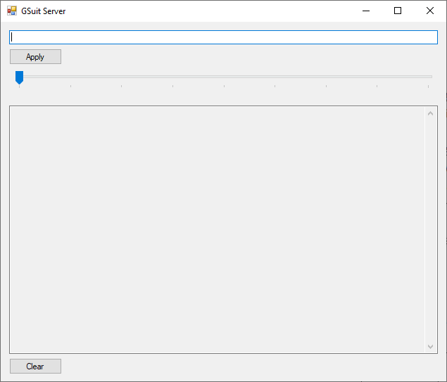
The GUI has a textfield to manually send commands to the Arduino, a box for debug output from the Arduino or the Server application itself, and a slider to test the G Force/pressure range.
The main components of the server are the serial port wrapper, the TCP socket listener, the message buffer, and the main form GSuit.

The serial port wrapper handles communication with the Arduino. It provides an interface to send and receive messages.
Noteworthy is the handling of an unexpectedly closed connection. This topic seems to be a bit tricky. I opted to simply catch and handle the exceptions resulting from accessing a disconnected SerialPort. See as an example the WriteSerialPort function.
public void WriteSerialPort(String message)
{
    try // isOpen doesn't catch if the serial plug was disconnected, causing an exception :(
    {
        lock (_serialPort)
        {
            if (_serialPort.IsOpen)
            {
                _serialPort.Write(message + ";");
            }
            else
            {
                TryOpenPort();
            }
        }
    }
    catch(Exception  e)
    {
        if(_serialPortError != null)
        {
            _serialPortError();
        }

        return;
    }
}
_serialPortError is a callback that will be handled in GSuit.
AsynchronousSocketListener
The message buffer gathers messages to be sent to the Arduino, sends them one by one (while avoiding successive duplicates) and receives responses.
public static void Run()
{
    String nextMessage = "";

    while (_isRunning)
    {
        if (_readBuffer.Count > 0)
        {
            nextMessage = _readBuffer.Dequeue();
        }
        else
        {
            lock (_writeBuffer)
            {
                lock (_readBuffer)
                {
                    _readBuffer = _writeBuffer;
                    _writeBuffer = new Queue<string>();
                }
            }
        }

        if (nextMessage.Length > 0
            && _lastSentMessage != nextMessage)
        {
            _debugPrintCallback.Invoke("message Buffer to Serial: " + nextMessage);

            _writeToSerialPortCallback.Invoke(nextMessage);

            _lastSentMessage = nextMessage;
            nextMessage = "";
        }

        String message = "";

        String fragment = _serialReadCallback();

        while (fragment.Length > 0)
        {
            message += fragment;
            fragment = _serialReadCallback();
        }


        if(message.Length > 0)
        {
            _debugPrintCallback.Invoke("Serial to message Buffer: " + message);
        }
    }
}
A double buffer (_readBuffer and _writeBuffer) is used to avoid message jams while waiting for responses.
The GSuit class scans all available serial ports for the Arduino and sets up the other components.
void InitSerialConnection()
{
bool found = false;

while (found == false)
{
    string[] portNames = SerialPort.GetPortNames();

    foreach (string portName in portNames)
    {
        try
        {
            SerialPort serialPort = new SerialPort();
            serialPort.PortName = portName;
            serialPort.BaudRate = 9600;
            serialPort.DtrEnable = true;
            serialPort.Open();

            if (serialPort.IsOpen)
            {
                serialPort.Write(SerialProtocol.ChallengeMessage + ";");

                Thread.Sleep(500);

                string response = serialPort.ReadExisting();

                serialPort.Close();

                if (response == (SerialProtocol.ResponseMessage + ";\r\n"))
                {
                    _portWrapper = new SerialPortWrapper();
                    _portWrapper.Init(portName);

                    AsynchronousSocketListener._socketCallback += MessageBuffer.SocketCallback;
                    MessageBuffer._writeToSerialPortCallback += _portWrapper.WriteSerialPort;
                    MessageBuffer._debugPrintCallback += WriteDebugLine;
                    MessageBuffer._serialReadCallback += _portWrapper.ReadSerialPort;
                    _writeToSerialPortCallback = _portWrapper.WriteSerialPort;

                    WriteDebugLine("GSuit found at " + portName);

                    found = true;

                    break;
                }
            }
        }
        catch (Exception e)
        {
            Console.WriteLine(e.ToString());
        }
    }
}
The Arduino is identified by sending a challenge message and waiting for the correct response message. Once a serial port responds correctly all other components are initialized. This function is also used when the SerialPortWrapper loses connection to find the Arduino again if it is reconnected.
DCS Plugin
The DCS plugin is responsible for passing on the current G-Force experienced by the player’s aircraft, similar to aookami’s DCS-GSOUND plugin. It consists of only the GSuit.lua file.
function LuaExportStart()
	socket = require("socket")

	host = "127.0.0.1"
	port = 56182

	lastTime = os.clock()
end

function LuaExportAfterNextFrame()
	delta = os.clock() - lastTime

	if delta >= 0.25 then
		connection = socket.try(socket.connect(host, port))
		connection:setoption("tcp-nodelay",true)

		socket.try(connection:send(string.format("%.3f<EOF>",LoGetAccelerationUnits().y)))

		lastTime = os.clock()
	end
end

function LuaExportStop()
	connection = socket.try(socket.connect(host, port))
	connection:setoption("tcp-nodelay",true)

	socket.try(connection:send("0.0<EOF>"))

	connection:close()
end
LuaExportStart is executed once the player enters a mission. Here it only initializes some variables for the TCP connection and message timing.
LuaExportAfterNextFrame is executed each frame. To throttle the message frequency to 4 per second the time since the last message is calculated. If the last message was more than 0.25 seconds ago the function opens a socket connection to the G-Suit Server and sends the current y-acceleration (vertical acceleration) as a string.
LuaExportStop executes when the player exits a mission. It just sends a force of 0 to the G-Suit Server to make sure the leg-wraps deflate.
To enable the G-Suit plugin this script has to be copied into DCS’ scripts folder, typically ‘C:/Users/Username/Saved Games/DCS.openbeta/Scripts/’. In this folder there is a script called Export.lua to which the following line has to be added
local dcsGs=require('lfs');dofile(dcsGs.writedir()..[[Scripts\GSuit.lua]])
Known Issues and further Development
After testing and using the G Suit during normal game play I can say in some regards it works as well or even better than I hoped. In some regards there is room for improvement as well.
For very low g forces it works better than I thought. The sensation of changing pressure is perceivable even for very small changes. It is not easy however to judge the actual g load just from the pressure sensation. This might change over time though as I get more used to it.
Given that pressure changes are easy to perceive the G Suit helps to maintain a desired g load once it is established.
Even though it is hard to judge the actual force magnitude, the difference between low forces and high forces is pretty noticable. Therefore it is easier to notice accidentally burning energy in stress situations.
I was worried that the pumps would be too slow for large and quick changes. This is far less an issue than I feared, but it could be better.
The pumps and drivers I am using have limited power, so the maximum possible pressure is not very high. A higher maximum would allow to make different g load easier to distinguish by feeling.
On the other hand, the G Suit as it is cannot create nearly enough pressure to risk injuries.
Trying to use more powerfull pumps should improve most of the issues mentioned. However this would make it necessary to mitigate the risk of accidentally turning the leg wraps into tourniquets.
Lastly I want to mention that the pumps create a not insignificant amount of noise. I tend to play with headphones, so it does not bother me much. It is audible with headphones on though, and other people might not appreciate the noise in the living room.
Acknowledgement
Thanks to my father for his riveting help help with riveting the case (and many other things).
A big thanks to my aunt who helped with making the leg-wraps (read: made the leg-wraps while I pretended to help sewing)
Also thanks to my uncle for his advice with the electronics.
Once again, thanks to Arduino for making programmable hardware that even an electronics-noob like me can use.
Resources
- https://learn.sparkfun.com/tutorials/serial-controlled-motor-driver-hookup-guide
- https://www.instructables.com/Serial-Port-Programming-With-NET/
- https://docs.microsoft.com/en-us/dotnet/framework/network-programming/asynchronous-server-socket-example
- https://docs.microsoft.com/en-us/windows/desktop/winsock/winsock-client-application
- https://github.com/aookami/DCS-GSOUND
- https://docs.arduino.cc/resources/pinouts/A000057-full-pinout.pdf
- https://www.instructables.com/Arduino-Nano-Altimeter-Using-GY-BMP280/


